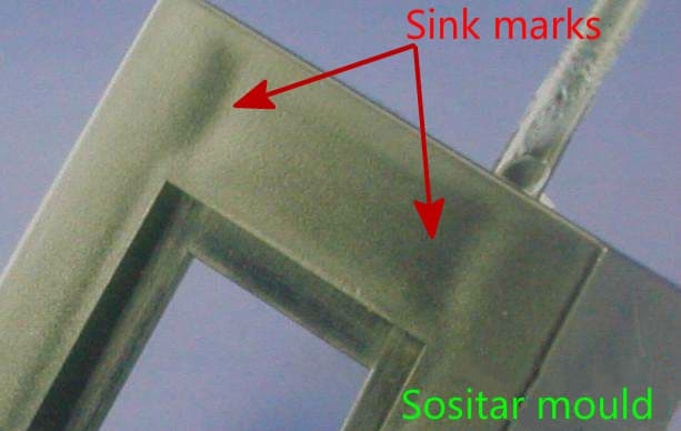
| Definition of Sink Marks: a localized depression (resembling a dimple or groove) on the surface of plastic injection molded product. 1. Product 1. The rib is too thick When the rib is thick, the location where the rib meets the bottom plate will also be thick, causing plastic concentration. During the cooling process, the ribs and plates around this location are first solidified, but the center of the rib and plate intersection still remains liquid. The plastic that solidifies later shrinks on the plastic that solidifies first, of which, the upward contraction creates a sucking-in effect on the surrounding plastic. Any location with a weak frozen layer (usually at the mold surface opposite to the rib) may collapse to cause a sink mark. The thickness of the rib is preferably 50% of that of the bottom plate, or even thinner. II. Mold 1. The temperature of the mold surface opposite to the rib is too high The temperature of the mold surface opposite to the rib is higher than its vicinity (this is usually the case, because the melt around here is concentrated, leading to a large heat load that keeps the mold temperature at a high level), while the frozen layer at this location is thin with insufficient rigidity. When the melt in the center is solidified, the residual stress may pull the thinner frozen layer inward to form a sink mark. The mold surface opposite to the rib must be particularly cooled to reduce the mold temperature here, so that the frozen layer is formed faster. When this layer is thick enough, the rigidity is increased to reduce the appearance of sink mark. You can start from the value recommended by the material manufacturer to set the mold temperature, and adjust the temperature at the decrement (or increment) of 6°C, then perform 10 shots. After the molding condition is stable, decide whether further adjustment is necessary based on the result. 2. The sprue, runner and/or gate are too small When the sprue, runner and/or gate are too small, resistant to flow is increased. If the injection pressure is not high enough, the cavity cannot be fully filled, resulting in a low melt density, hence higher possibilities for the appearance of sink marks. 3. Improper gate quantity or location Improper gate location or quantity increases the flow length, causing the flow resistance to be too high. If the injection pressure is not high enough, the cavity cannot be fully filled, resulting in a low melt density, hence higher possibilities for the appearance of sink marks. Sometimes, due to mold manufacturing defects, it is difficult to solve the surface shrinkage or depression of a molded product near the cylinder (ejector sleeve), no matter how hard you adjust the machine. Even if it is barely solved, the molded product is already covered with flashing. There are two reasons for the serious shrinkage at the ejector sleeve location: When the ejector pin is too short or too thin, the part of the molded product at the bottom of the ejector sleeve is too thick (for example, more than 4mm, while the wall thickness of other parts of the molded product is only 2mm), shrinkage-related problems will be unavoidable, and the thicker, the more difficult it is to solve it. Even, this cannot be solved by adjusting the machine, which is mostly the case in real-world production. When the ejector pin is too long, the wall thickness of the molded product at the end of the ejector pin is too thin (for example, less than 0.3mm), leading to a very low thermal strength of the plastic product at this location. When the molded product is ejected from the mold, the ejector pin is drawn out, forming a vacuum inside the pin hole. Then, the outside atmospheric pressure will dent the surface of the injection molded product, creating a depression, i.e., sink mark. Therefore, before solving such a shrinkage problem, the molded product should be cut first for observation, to see whether this part the injection molded product is too thick. Usually, it should not be thicker than the wall thickness of the product, otherwise the ejector pin needs to be lengthened until the shrinkage is solved; if it is found that the depression is too thin (usually no less than 0.5mm), the ejector pin can be ground shorter with a grinder, so as to solve the depression problem. Besides, applying a mold release agent on the ejector sleeve can also be used as an assistive means to enhance shrinkage improvement, because the mold release agent helps cool the ejector pin, enhancing the cooling effect of this location, and thereby reducing the degree of shrinkage, while also preventing the formation of vacuum when the pin is ejected, since the mold release agent is able to generate a little gas. III. Injection Molding Machine 1. The barrel temperature is too high When the barrel temperature is too high, the melt density is low. During the cooling process, the melt close to the surface of the cavity will first be solidified into a frozen layer. The volume of the plastic shrinks, and the melt density in the center of the cavity is smaller. When the melt in the center is gradually solidified, the center of the cavity will become hollow, of which the inner wall will be full of tensile stress. If the frozen layer is not rigid enough, it will collapse inward to form a sink mark. With lowered material temperature and increased melt density, the possibilities for the appearance of sink marks will be minimized. 2. Insufficient cooling time With insufficient cooling time, the plastic frozen layer will not be thick enough to resist the pulling force generated when the inside melt solidifies and shrinks, thus forming a sink mark. Material suppliers are able to provide recommended cooling time values for different plastics and product thicknesses. 3. Insufficient cushion and/or holding pressure With insufficient holding pressure or holding time, the plastic in the cavity will not be compacted due to the low pressure or insufficient supplementary material, leading to a low density, and accordingly a sink mark. When the cushion becomes 0, the screw will not move further in the end, while the pressure will decrease when the melt is cooled and contracted, but the screw cannot maintain the pressure, resulting in insufficient holding pressure and a high possibility for sink marks. The cushion needs to be at least 3mm, the holding pressure should be sufficient, and the holding time should be at least 2s. 4. Non-return valve failure The non-return valve prevents the melt at the front of the in-barrel screw from flowing back during the injection molding process. When the screw pushes a fixed amount of material forward, if the non-return valve is worn, cracked or improperly seated, the melt may slip past the clearance between the front end of the screw, the non-return valve and the barrel, and flow back, causing the screw to bottom out and the cushion to disappear, thus increasing the chance of sink marks. Remove the non-return valve from the front end of the screw and check the contact surface. If there is burned plastic on the surface, use a wire brush to remove it; do not use a torch to burn off the plastic, because the high heat will soften the valve metal, causing accelerated wear. If nickels, cracks or pits are found on the contact surface, the defective parts should be accordingly replaced. Equipment related causes: ①. The hopper is interrupted; ②. The hopper neck is partially or completely blocked; ③. Insufficient feeding amount; ④. The feeding control system is not working properly; ⑤. The plasticizing capacity of the injection molding machine is too small; ⑥. Abnormal injection cycle caused by equipment. Molding condition related causes: ①. The injection pressure is too low; ②. Injection pressure loss is too high during the injection molding cycle; ③. The injection molding time is too short; ④. The holding time is too short; ⑤. The injection rate is too slow; ⑥. The material flow in the cavity is interrupted; ⑦. Varying rate of mold filling; ⑧ Abnormal injection cycle caused by molding conditions. Temperature related causes: ①. Increase the barrel temperature; ②. Increase the nozzle temperature; ③. Check the millivoltmeter, thermocouple, resistance heating coil (or far infrared heating device) and heating system; ④. Increase the mold temperature; ⑤. Check the mold temperature controller. Mold related causes: ①. The runner is too small; ②. The gate is too small; ③. The nozzle hole is too small; ④. The gate location is inappropriate; ⑤. Insufficient number of gates; ⑥. The cold slug well is too small; ⑦. Insufficient venting; ⑧. Abnormal injection cycle caused by mold; Material related causes: Poor fluidity of the material. | ||