What are the guiding and positioning mechanisms of an injection mold?
Collectively speaking, the mold guiding mechanism is the component of an injection mold that aims to ensure the smooth movement and accurate reset of each moving part during mold opening and closing, so that they are not misaligned and deformed under the action of the clamping force of the injection molding machine and the expansion of the molten plastic. Among them, the mold structure that ensures that the moving parts travel as per the predefined trajectory is referred to as the guiding system, while the structure that ensures the relative positional accuracy between the mold core, cavity and the moving parts is referred to as the positioning system.
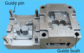
Guiding parts include guide pins and guide bushes, etc.
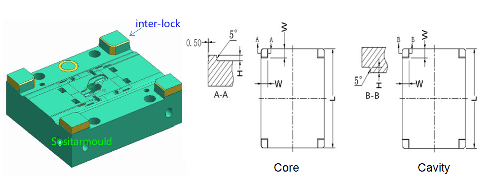
Positioning parts include side lock and interlock, etc.
Why Is Guiding Mechanism Necessary
1. The mold opens and closes repeatedly;
2. High precision requirements;
3. High requirements on mold service life;
4. Under high temperature during production;
5. Under high pressure during production.
3. Types of Mold Guiding & Positioning Mechanisms
Guide pin / guide bush, including:
(a). Guide pin / guide bush of A / B plates: guides the core and the cavity.
(b). Guide pin / guide bush of the stripper and A plates: guides the stripper plate and A plate in the core of a 3-plate mold; also guides the B plate of a simplified 3-plate mold.
(c). Guide pin / guide bush of ejector retainer plate: guides the ejector retainer plate and the ejector base plate.
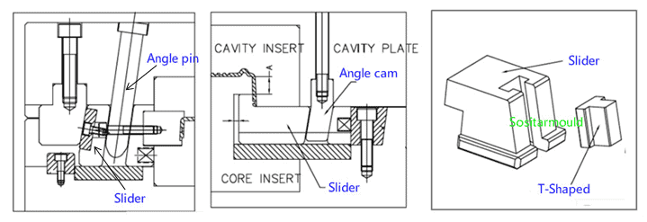
Guide pin and guide groove for the siders:T-shaped groove of the slide, square hole of the angled ejector pin, and T buckle of the inclined slide, etc.
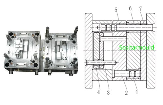
Mold Guiding System Design
The fit between the guide pin and the guide bush is a clearance fit, of which the tolerance is H7/f7.When the mold closes, make sure that the guiding parts first come in contact with the core and cavity.Since the plastic part is usually retained in the mold core, to facilitate part release, the guide pin is usually installed in the cavity.
Guide Pin Design
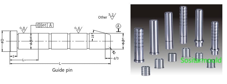
(1). Shape: Guiding parts and oil sump;
(2). Material & Thermal Treatment: The surface of the guide pin is cemented quenching treated.
(3). Tolerance & Fit: The fit between the guide pin and guide sleeve shows a tolerance of H7/f7.
(4). When the mold closes, make sure that the guiding parts come in contact first.
(5). Since the plastic part is usually left in the mold core, the guide pin is usually installed in the mold cavity to facilitate mold release.
Guide bush Design
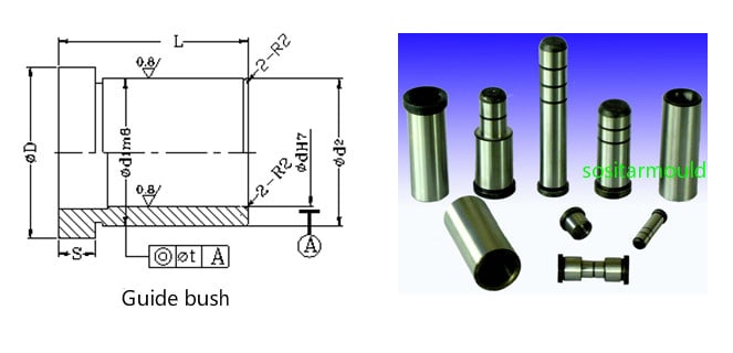
(1). Shape: See the fig.
(2). Material: The guide sleeve can be made of the same material as the guide pin, or wear-resistant materials, such as copper, but its hardness should be kept slightly lower than that of the guide pin.
(3). Fastening and fit accuracy: usually inserted into the mold plate by adopting the H7/m6 transition fit; the straight guide sleeve is inserted into the mold plate by adopting the H7/r6 interference fit.
Design of guide pin & guide bush between mold core and cavity
(1). How the guide pin and guide bush are put together

(2). Guide pin length design
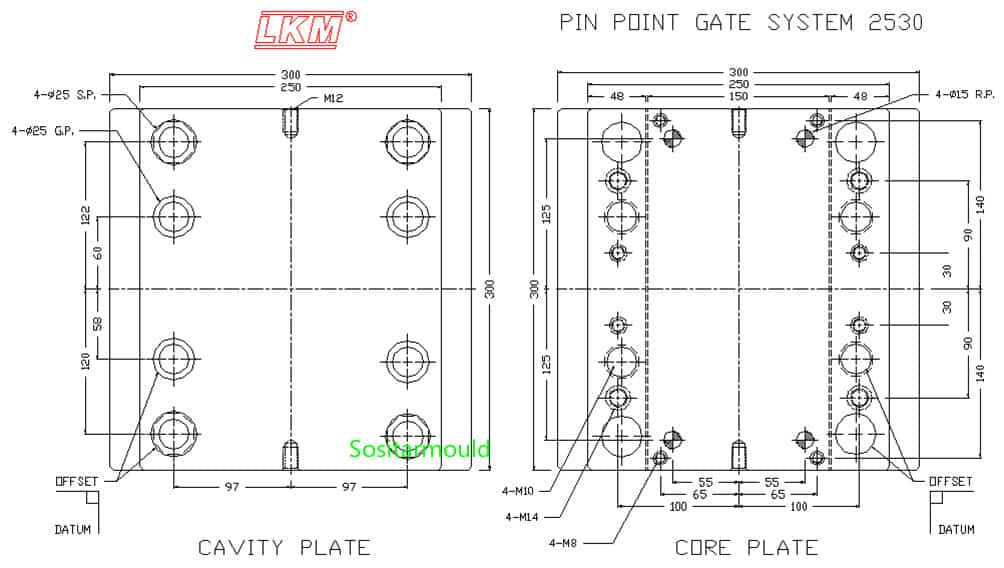
(3). Number and layout of guide pin and guide bush:
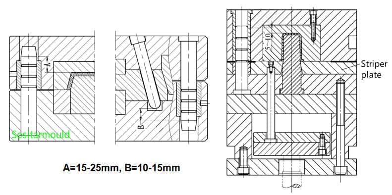
Cavity guide pin & guide bush design of a 3-plate mold
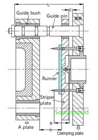
1. How to determine the support pin length:
L = A plate thickness + stripper plate thickness + face plate thickness + A + C + 30
Among them: A = total gate height + 30mm,
C usually ranges from 6 to 10mm.
2. Support pin diameter
The diameter of the cavity guide pin of a 3-plate mold has been standardized with the mold base. Usually, there is no need to change it. However, the guide pin needs to bear the weight of the A plate and the stripper plate, so in the following cases, the guide pin should be thickened by 5mm or 10mm so as to protect it from deformation.
Ejector guide pin & guide bush design
1. When is ejector guide pin needed?
(1). There is an ejector sleeve;
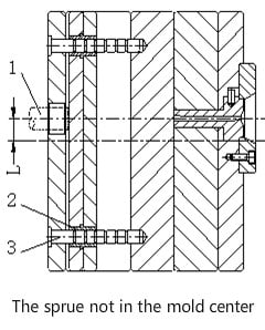
(2). The sprue bushing is eccentric;
(3). Several ejector pins are less than 2mm;
(4). Ejector pins on one side is more than those on the other side;
(5). There is a lifter;
(6). Raised spacer plate;
(7). Two-stage ejection with double ejector plates
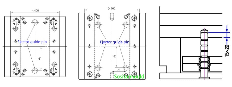
2. The size and quantity of ejector guide pins:
(1). The mold base with a width of less than 400mm uses 2 ejector guide pins with a diameter equal to that of the return pin or 5mm larger than that of the return pin;
(2). The mold base with a width of more than 400mm uses 4 ejector guide pins with a diameter equal to that of the return pin.
Mold Positioning System Design
Functions of positioning system
The mold positioning system is to ensure that the mold core and cavity are accurately positioned during mold closing and injection molding, share the lateral pressure on the guide pin, and improve the rigidity and matching accuracy of the mold.
Where the positioning system is used
A positioning system must be designed in the following circumstances: (1)Large mold: the mold is more than 400mm wide; (2)Molds with deep cavities, or with high precision requirements for plastic parts; (3)The cavity is eccentric; (4)There are multiple shut-offs; (5)Designed with asymmetric side core pulling; (6)The plastic part is extremely asymmetric, and the expansion force deviates from the center of the mold; (7)The parting surface is an irregular inclined or curved surface; (8)The product quantity is large, with high requirements for mold service life; (9)When the core and cavity inserts need to be outsourced, to ensure the positional accuracy of the inserts, a cone locking block is usually designed for positioning.
Types of Positioning Structure
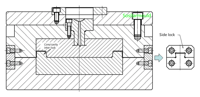
1.Side Lock:
The side lock is a supporting positioning mechanism of the guide pin and the guide sleeve. It is mostly used for large-size (more than 400mm wide) molds with a deep cavity, and plastic parts requiring high precision. Installed on the four sides of a mold, the side lock falls into two categories, straight lock (upper right) and draft lock (lower right).

Core / Cavity Interlock:
There are two types, i.e., cone positioning between A and B plates, and core / cavity interlock. The function and application of the cone positioning between A and B plates are the same as the side lock, but it is installed between A and B plates.The core / cavity interlock is located at the four corners of the mold core and integrated with it. Interlock between A and B plates:

2. Interlock between Core/Cavity Inserts: