Gate system definition:
The passageway between the beginning of the spure and the cavity. The gating system is composed of the sprue, runners, the gate and the cold slug well.
Purpose:
The purpose of the gating system is to inject the molten plastic, under high temperature, high pressure and high speed conditions, into the mold cavity to form a product though the nozzle of the injection molding machine.
Design Principles of Gating System
a. Guarantee the external and internal quality of plastic products;
b. Increase the molding speed and reduce the molding cycle;
c. Balanced material feed, low heat loss.
Sprue(runner inside the sprue bushing )
Generally speaking, the location of main runner entrance should coincide with that of the mold center.
(1) Design Principles:
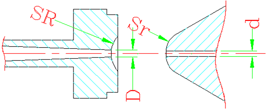
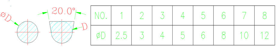
D = d+(0.5~1)
SR= Sr+(1~2)
40~160t Sr=10
200~450t Sr=19
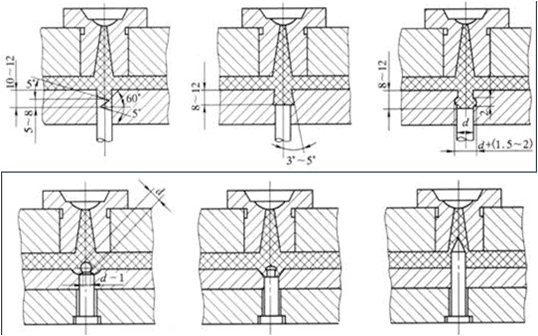
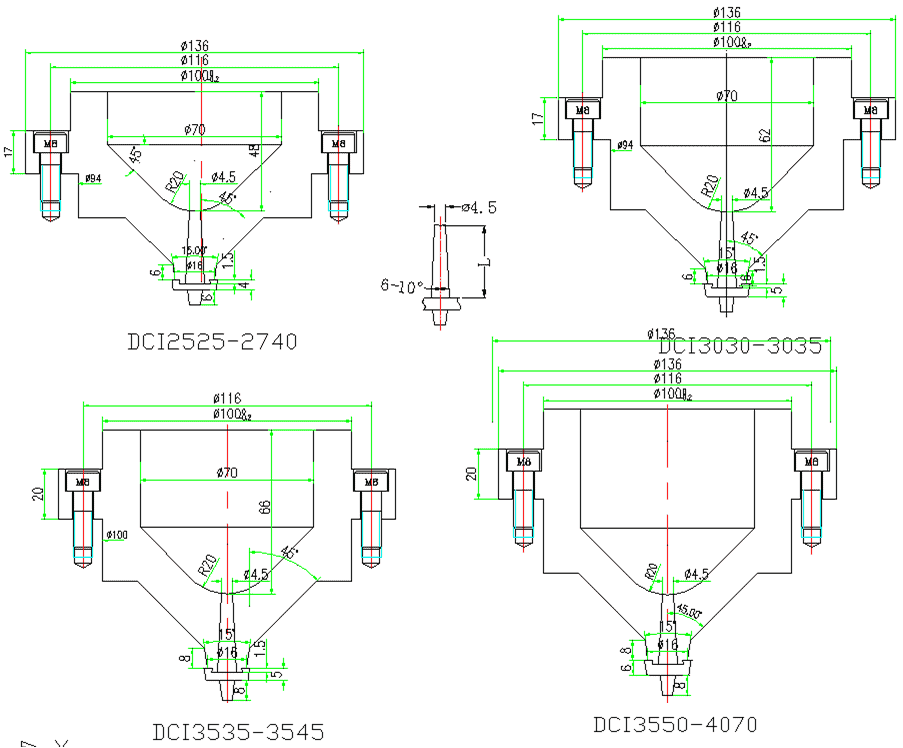
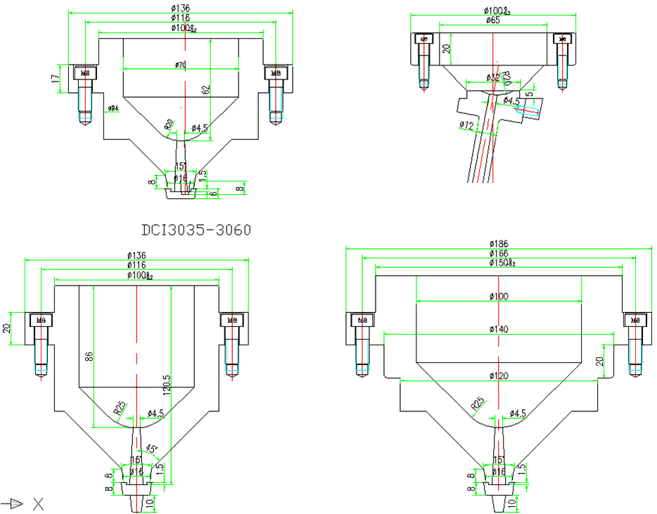
2)Types of Sprue Bushing (Ingate Sleeve)
a. Sprue Bushing Types of Two-plate Mold
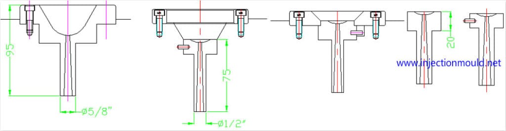
b.Sprue Bushing Types of Three-plate Mold
What is the runner ?
The runner is a passageway connecting the sprue and the gate.
Considerations for runner design:
1). The requirements for product geometry, wall thickness, dimensions, stability, features and external quality.
2). Plastic types, fluidity, melting temperature, solidify temperature and shrinkage.
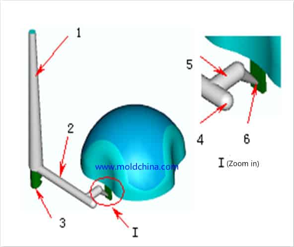
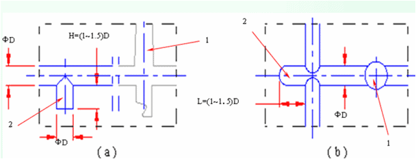
3). If the runner is long, a cold slug well should be set at the end to hold the cold slug and prevent air penetration. Generally, a sprue puller is designed in the cold slug well to facilitate sprue release.
4). Puller and release of the sprue and the runner.
5). The layout of the cavity, the location and type of the gate.
6). Runner design should take the smaller value in the beginning, to allow for mold modification after mold testing.
7). If there are many branch runners, a sprue spreader can be considered, which helps avoid direct impact of the molten plastic on the cavity, as well as sharp turning of the melt to ensure a smooth flow.
8). Runners are usually distributed in a balanced manner. In special circumstances, imbalanced methods can be adopted, requiring that all cavities are fed simultaneously in a balanced way, with a compact arrangement and a short flow range, so as to reduce mold size.
Runner Design Requirements:
1). Minimize temperature and pressure loss.
2). The condense of the branch runner should come later than that of the product, so as to facilitate pressure transfer.
3) .The molten plastic coming from the spure is able reach all gates in the shortest flow and in a balanced way. At the same time, ensure that the melt fills all cavities quickly and uniformly.
4). When considering the layout of the cavity runner, it is the best to make the geometric center of the total projection area of the cavity and the runner on the parting surface coincide with the center of the clamping force.
5) The runner is usually designed either on the core or the cavity.
6). Easy for tool processing.
Types of Runner
There are three commonly used runners cross section designs (see the diagram)
Common Sectional Areas of Branch Runner
a. Circular and U-shaped runners
b. Trapezoidal runners

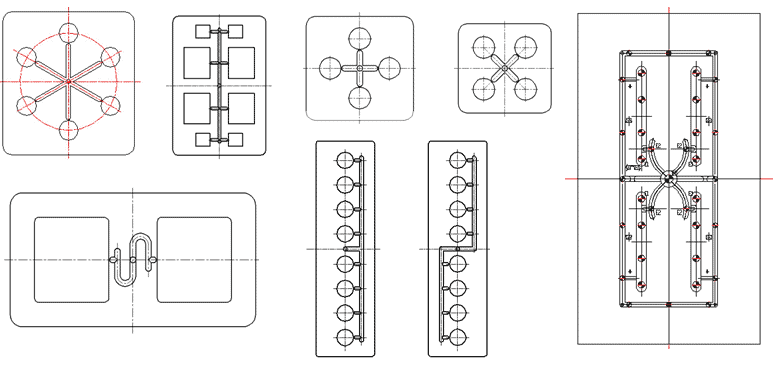
Arrangement of Runners
Fall into balanced and imbalanced arrangements on basis of characteristics
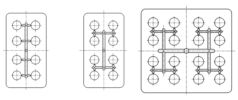
Fall into O, H, X and S-shaped arrangements on basis of layout
Scenarios that Need Auxiliary Runners
Chrome plating, secondary injection and other subsequent processes
Secondary runner is able to improve molding quality
Convenient for packaging
To keep the plastic part on the core
Cold Slug Well
It is designed to remove the cold slug generated at the melt front due to the contact between the nozzle and the low temperature mold, so that the cold slug won’t enter the cavity
The types of cold slug well
Cold Slug Well with Ejector Rod at the Bottom