Selection of Gate Types for Commonly Seen Plastic Products
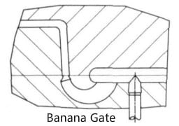
1. Axially symmetric products, such as gears, blades and the like have a higher rotational speed during operation, so the surface should be smooth and flat without air bubbles, to ensure resistance to wear. Such products require that the functional surface (usually the sides) should not be defective, and the bottom surface needs to be flat, so the gates of such products should be as small as possible and concealed, so it is not suitable to apply the submarine gate and some other forms that are not easy to remove. It is better to use the banana gate or the point gate.
2. With regard to cup-shaped products, like small casings and capacitor containers, etc., gates should be designed near the base to avoid air cavities. Generally speaking, a point gate or a submarine gate is designed near the base.
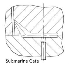
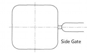
3. As for slender items, the design of gate should follow the longitudinal direction rather than in the transverse direction, or in the center. Usually, the side gate, submarine gate and banana gate are applied.
4. Concerning spoke or mesh products, the multiple point gate is used.

5. Electroplated plastic products usually adopt the side gate which will be ejected along with the plastic product. Set plating points in the runner, and remove the gate after plating.
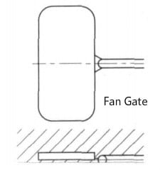
6. Flat plastic products often apply the fan gate. This kind of gate is able to guarantee even material feeding, with no weld marks, but great ventilation.
7. Plastic items with metal inserts should allow the melt to flow around the insert smoothly, so as to minimize inaccuracy of insert position. The side gate or the submarine gate is often used.
The Principle for Selection of Gate Position
The gate position is mainly determined as per the geometry and technical requirements of the product, as well as the analysis of such factors as the flow status, feeding, shrinkage compensation and ventilation of the melt in the runner and the cavity. Generally, the principles below should be followed:
1. The gate should be located in the thicker section of a plastic product, so that the molten plastic is able to flow from the thick section to the thin section to ensure sufficient filling;
2. Minimize the travel distance, directional changes, and energy loss of the melt flow, so as to minimize pressure loss;
3. Helpful for eliminating air in the cavity;
4. Prevent weld marks on the surface of plastic products. Especially for circular or cylindrical plastic products, a cold slug well should be designed on the gate surface, where the melt fronts meet;
5. The gate location for a plastic injection mold with a slender core should be far from the mold core, so as to prevent the core from deformation caused by the impact of melt flow;
6. When forming a large or flat plastic product, to prevent warpage and insufficient filling, the multi-gate design should be employed;
7. The gate should be designed at locations that do not affect the appearance of a plastic product, such as the edge or the bottom;
8. When designing a multi-cavity plastic injection mold, consider the balance of the gate by referring to the balance of the runner, and try to make the melt fill each cavity concurrently and evenly.
The design and location selection of the gate directly determines whether the molded product can be created satisfactorily with great quality. The type and location of the gate not only greatly influences the molding properties and quality of a plastic product, but also affect the overall structure of the mold. Therefore, the rational selection of gate type and location plays an important role in improving the quality of a plastic product. The gate type and location of a mold should be selected according to the structure, process characteristics and quality requirements of the molded plastic product by taking the process characteristics of the plastic product and the raw plastic material, as well as the flow status of the molten plastic in the cavity, and the molding process conditions into consideration.